Page 9 of 13
Re: Chris' 200 20v Revver Project
Posted: Tue Oct 07, 2014 10:02 pm
by loxxrider
Aktapod wrote:loxxrider wrote:After a reply from Jeff, I now know that the diesel crank is significantly heavier (bigger lobes) to deal with the heavier pistons. This will cause complications when it comes to balance the engine, and more. So, it looks like that is going to have to be out due to added complexity and custom work required.
Would this go the same for the Eurovan 95,5 crank?
I'm not sure, but I do think it applies at least partially. This isn't anything to worry about on an 8,000 or 8,500 RPM engine. On 9500 or 10k it is though.
alxdgr8 wrote:loxxrider wrote:Those are awesome! I wonder what they are used for?
I don't want to use a 92.8 crank because it is too rare and expensive. I don't see why the 95.5 in a tall deck would be any worse for revving than an 86.4 in a regular block. They have the same rod ratio, but longer rods!
They're from a former gasification plant that's now a park here in Seattle:
http://en.wikipedia.org/wiki/Gas_Works_Park
There's a good 7'+ tall

Cool! Thanks
As usually happens when I get to thinking about this kind of thing, I started applying some math and stuff to the situation. I'm curious about how the acceleration of the piston is affected in all of these setups. I'm feeling super smart about working through the equations on my own to come up with these plots. I thought they looked wrong at first, but then checked them against similar plots from others and they are correct! 8) The values in the plots are arbitrary for now, but take a look and try to understand the relationships. I will post overlays of different rod ratios later and will add some engine speed context.
This is for a stock AAN or 3B engine (86.4 mm crank and 144 mm rods)
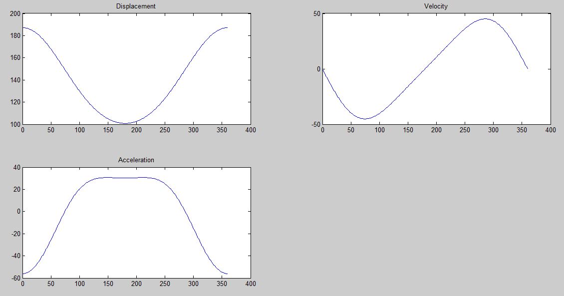
- Piston Motion Plots.JPG (48.95 KiB) Viewed 50469 times
Kevin, I have homework for you. If you have the time, see if you can come up with the equation of motion for a piston in an engine. Then you can get it's velocity and acceleration at any point in the rotation. I had fun doing it :shrug:
Re: Chris' 200 20v Revver Project
Posted: Tue Oct 07, 2014 10:06 pm
by loxxrider
Dutchbroracer wrote:I still have this BW Air Werks s400sx4 laying around. (S475) No way in hell will I ever have a head or dry sump to run it. Id make a killer deal. Brand new, just balanced last year.
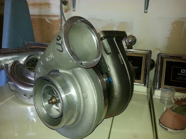
Compressor:: (cold side) Over 98 lb/min
- Wheel: 75mm Inducer / 100.8mm Exducer w/ Extended Tip Technology <
- Housing: (select from menu)
#1. 5.00" ported anti-surge air inlet / V-band flange charge pipe outlet.
#2 Large High Flow Race Cover w/ 5.50" air inlet/ 3" slip-on charge pipe outlet with ballistic attenuator. (has tapered funnel/velocity stack fitted on the inside of the air inlet)
::Turbine:: (hot side)
- Wheel: 95.7mm Inducer / 88mm Exducer (Made of Inconel 713 for high-temperature operation)
- Housing: Large T6 Divided twin scroll inlet/ 5.00" V-band flange downpipe discharge
- A/R: 1.32 A/R
I'd love to, but that hotside is WAAAAY too big! I'm still debating on the turbo size I want. That is at the top of the range on coldside, but not out of the question. The hotside is prohibitively huge though. :(
Re: Chris' 200 20v Revver Project
Posted: Tue Oct 07, 2014 10:47 pm
by Aktapod
loxxrider wrote:Kevin, I have homework for you. If you have the time, see if you can come up with the equation of motion for a piston in an engine. Then you can get it's velocity and acceleration at any point in the rotation. I had fun doing it :shrug:
Haha, joke's on you! I actually did that last year sitting in some class!

But really, I was idly sitting in lecture, and a thought popped into my head as to what the top speed of my pistons was. Did some trig to find the position and derived with respect to crank position (I was also pretty proud at the time). Of course, this led to my next quest, which, despite my extensive research, remains unresolved. So,
your homework, if you have the time, is to help me determine what gives different engine configurations their distinct tones, and why. The "why" is the important part.

Re: Chris' 200 20v Revver Project
Posted: Tue Oct 07, 2014 11:21 pm
by All_Euro
Aktapod wrote:... help me determine what gives different engine configurations their distinct tones, and why. The "why" is the important part.
This, I would love to know as well!
Re: Chris' 200 20v Revver Project
Posted: Wed Oct 08, 2014 3:53 am
by PRY4SNO
Aktapod wrote: So,
your homework, if you have the time, is to help me determine what gives different engine configurations their distinct tones, and why. The "why" is the important part.
The answer, young padawan, is firing order.
Re: Chris' 200 20v Revver Project
Posted: Wed Oct 08, 2014 4:25 am
by PRY4SNO
Some existential life answers here...
http://www.motorgeek.com/viewtopic.php?t=19077
Although this isn't the holy grail.
Re: Chris' 200 20v Revver Project
Posted: Wed Oct 08, 2014 6:56 am
by ChrisAudi80
Re: Chris' 200 20v Revver Project
Posted: Wed Oct 08, 2014 10:21 pm
by loxxrider
That's funny, I found that last night when doing some educational reading and searching for topics on rod ratio.
Kevin, this is a question I've often asked myself too. I think he's got it right about firing order. That is the major determining factor in the way an engine sounds. HOWEVER, that isn't the final answer. As you probably know, the same engine with the same exhaust and same everything can sound much different with varying cam timing and even ignition timing. An engine with not enough timing in it can be audibly "flat" compared to the same engine in proper tune. 7A cams make for a higher pitched sound than 3B cams for example. Ultimately, these things all change the way the sound waves combine to create the overall sound. Some cancel each other out, sometimes they combine, other times they may form a "beat" phenomenon, etc. To get into the details of it would probably require a vibes analysis! This is the most I've ever thought about it though, and I think it is pretty logical.
Here are some comparison plots. Green is 160 mm rod in a tall deck with 86.4 crank. Blue is 144 mm rod in a normal block with 86.4 crank (I know the color choices are terrible, will change that on the next go). Note that peak acceleration and therefore peak stress is at TDC, not BDC. The plots are all in the angle domain. I will convert them into the time domain later (it's just a matter of scaling) to give you guys some palpable values of accelerations and therefore forces. I think the important thing to note is that in this particular case the difference in stresses will not be that much for a given RPM. However, that small difference in stress may be a big deal if the hardware is close to it's physical limitations.
Also quite noteworthy is that funny looking hump at bottom dead center on the acceleration graph. That is something that occurs in most engines and is dependent on the rod ratio. Increasing the rod ratio minimizes or completely eliminates that. The reason this is important is because this can cause some secondary vibrations. I have to give this part some more thought.
Overall comparison
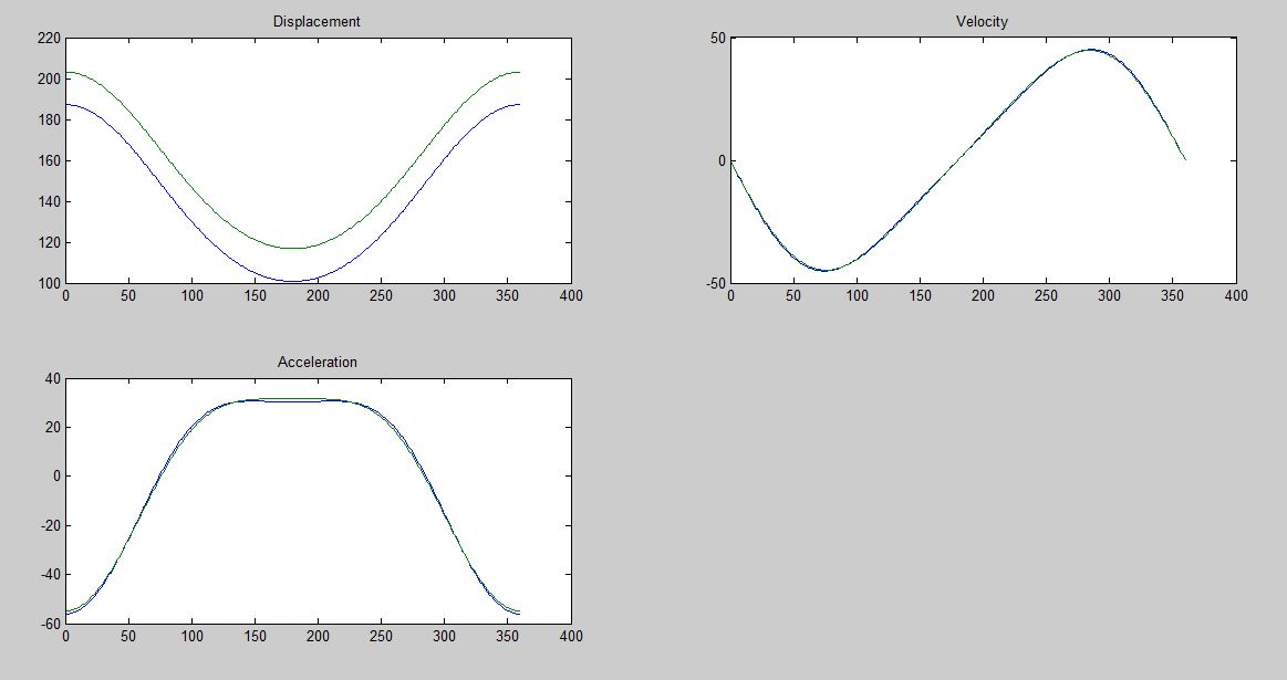
- 144 vs 160 mm rod.JPG (52.41 KiB) Viewed 50416 times
Position - Blue 144 mm rod in regular block with 86.4 crank vs Green 160 mm rod in tall deck with 86.4 crank
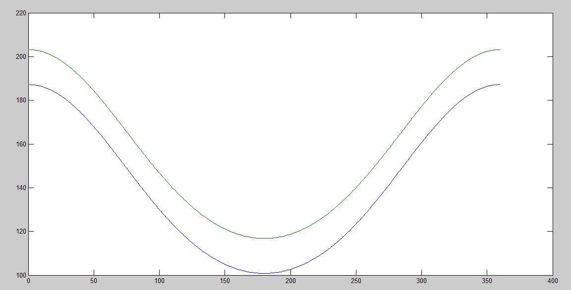
- 144 vs 160 position.JPG (43.12 KiB) Viewed 50416 times
Velocity - Blue 144 mm rod in regular block with 86.4 crank vs Green 160 mm rod in tall deck with 86.4 crank
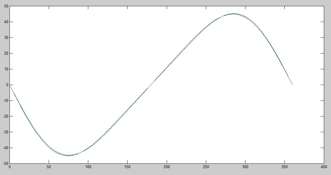
- 144 vs 160 velocity.JPG (39.96 KiB) Viewed 50416 times
Acceleration - Blue 144 mm rod in regular block with 86.4 crank vs Green 160 mm rod in tall deck with 86.4 crank
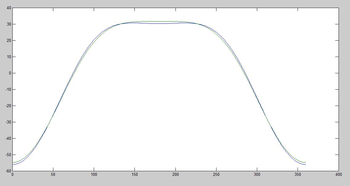
- 144 vs 160 acceleration.JPG (40.67 KiB) Viewed 50416 times
Re: Chris' 200 20v Revver Project
Posted: Wed Oct 08, 2014 10:29 pm
by loxxrider
That is quite interesting isn't it? Hank mentioned the same thing to me when we were discussing this recently. I brought this up with Jeff G. too, and he commented that different engines are made for different purposes. The way this was built will not necessarily be suitable for my needs. The small valve thing is super interesting, but I don't quite get it so I can't discuss it very intelligently. I guess something to do with increasing velocity through the port to help spool the turbo. I don't think that will fly at 10k though.

Re: Chris' 200 20v Revver Project
Posted: Thu Oct 09, 2014 5:15 am
by ChrisAudi80
loxxrider wrote:
That is quite interesting isn't it? Hank mentioned the same thing to me when we were discussing this recently. I brought this up with Jeff G. too, and he commented that different engines are made for different purposes. The way this was built will not necessarily be suitable for my needs. The small valve thing is super interesting, but I don't quite get it so I can't discuss it very intelligently. I guess something to do with increasing velocity through the port to help spool the turbo. I don't think that will fly at 10k though.
I thought this engine build approach compared to your plans was interesting. It is built to rev (9600 max IIRC), dry sump, 1120hp.
The transmission set up is more interesting for Aaron I think, even though he is going RWD.
In all, a very interesting car.
Re: Chris' 200 20v Revver Project
Posted: Thu Oct 09, 2014 8:09 am
by loxxrider
I think the max specs are similar, but that engine is not built to make peak power at peak RPM. Yeah, it will rev to 9600, but they don't bother because it wont flow well enough there (I'm assuming). Again, I don't really feel educated enough on this subject to make any more comments. I could be totally wrong! I think Jeff's numbers and especially the shape of his power curve speak to his credibility on this subject though. His engine is still making power at 10k!
Re: Chris' 200 20v Revver Project
Posted: Thu Oct 09, 2014 9:44 am
by loxxrider
OK, better plots have arrived. My MATLAB skills are constantly in development lol
For the nerds out there, you can take the max value on the acceleration plot and multiply by mass (what mass to use depends on where you want to find the stress) to get force due to piston movement (does not account for cylinder pressures, friction from sidewall forces, etc). This is still quite relevant however if we assume that all variables other than those affecting rod ratio are the same. This is a good assumption too, especially at TDC where peak stress
due to piston dynamics is located. Then, you can use mechanical properties of the component in question to calculate the stress in the component (due to piston acceleration).
I will probably do a first order approximation of this with respect to rod bolts. For example, you can just take the mass of the piston and rod without the big end cap and multiply by acceleration to get force. Then multiply force by x-sectional area in the region of interest. The fact that peak stress happens at TDC makes things simple! - no angles to deal with. This way it is possible to know the delta in stress induced by RPM which will be useful for determining if one combo will be significantly better than another. If I can determine that the difference is acceptable for the worse case (the short rod), then I will elect to use that due to its superior torque/spooling capability.
The next thing on the horizon is looking at what that funny "M" shape at TDC does to engine vibrations. That could be a bit too much to get into for now though. We'll see how bored I am... or how hard I want to try to figure it out.

Re: Chris' 200 20v Revver Project
Posted: Thu Oct 09, 2014 12:35 pm
by FRP
Hi Chris
All interesting stuff but I am wondering if you are too deep in the forest here to see all of the trees?
Unless these models have values for dynamic combustion forces I think they are of somewhat limited benefit. When factory engineers set up a balancing paradigm they factor in the dynamic forces of compression, power, exhaust and intake. Then they make a compromise with a pretty good idea of where the remaining primary and second and third order vibes will occur plotted against their knowledge of the intended use, how the motor will be mounted, any external damping in the flywheel and crank balancer etc. along with where the engine will spend the majority of its time, rpm wise, during normal use.
If these models are based on pure angle and speed equations that don't account for varying pressure in the cylinders they will miss the huge differences that occur between full acceleration and full decell. They would also fail to address the huge order of magnitude differences between dynamic conditions in an NA vs. Turbo motor.
As an example I can assure you that in a turbo motor, under boost, the max FORCE seen by the piston and rod assembly occurs at BDC where it is always being pushed towards the crank by the power stroke or cylinder filling boost pressure and is under the varying dynamic counter forces of compression or ignition damping its motion at TDC. Then if the throttle closes suddenly all this would reverse big time.
My point is that the beast is so GD dynamic that everything the engineers do is a compromise so I would not put too much stock in one particular model. Rather I would suggest deciding what power characteristics are most desirable for your application and focusing on the major factors that effect reaching that goal. If you expect to spend a lot of time with your engine operating over 8K rpm and don't really care about power below say 5.5K then by all means go with the tall rod ratio. I think the ultimate compromise and best over all power would be obtained with the 92.8 crank in the tall block. That is definitely what I would build if I could get my hands on a factory 92.8 crank.
Now if I was building a street car and wanted a killer usable street power band (max power under the curve) I would put the 92.8 crank in the standard 220 mm deck height block with 144 rods and a raised pin height and really kick some ass. BTW just remember, that combination is what has kept the Audi / VW 2.0 T motor on the "Wards 10 Best Engine" list for 9 years running. You could red line it at 7800 rpm and make huge power and torque numbers that would just kill everything else - in the real world.
Also, I am having a crank made for an Dodge SRT 4 standing mile car. If the quality and execution are what I expect, I will be sending them an AAN crank for evaluation and cost estimate to reverse engineer it in a 92.8 stroke. It would be American 4340 Chrome steel, made in America, machined in America real deal stuff. I would be interested to know what any of you think the "market would bear" for such a quality piece. Cheers.
Re: Chris' 200 20v Revver Project
Posted: Thu Oct 09, 2014 2:22 pm
by 20VAvant
I love this forum.
There is such a vast amount of knowledge that is not comparable to any other forum.

Re: Chris' 200 20v Revver Project
Posted: Thu Oct 09, 2014 2:39 pm
by loxxrider
To respond to your last point first, I would say it probably isn't worth it. 99% of Audi enthusiasts (even the craziest ones) are happy with the selection of stock cranks. There might be one or two in the US, but most of the people interested would probably be in Scandinavia. Those guys do seem to be happy with stock cranks though. I think the market would bare 10 cranks max.
Jeff, I totally understand what you're saying here. I fully grasp the complexity of the system, as I have some background in vibes analysis in jet engines. The analysis I just did was merely a single component of a big force sum. I didn't mean to say that max stress is at TDC, just that the component of stress due to piston acceleration is at the maximum there. At (and near) TDC, the rod (for example) sees tensile stress from the piston motion, but also sees compression due to compression ratio and, more significantly, rapid gas expansion as the mixture explodes.
After approximately 90 degrees, the load on the rod goes into compression due to piston motion AND due to expansion of gasses, etc. as you mentioned. I agree, that the overall max stress on the rod is not at TDC for this reason. I don't agree that this occurs at BDC though as by that point the piston gets to BDC, the pressure has been relieved a bit due to volume increases. I can also make a first order model of this for an interesting approximation of the situation. It's all in good fun anyway. This is more of a learning exercise than anything, and I've learned a TON in the last day. If it leads to some information that helps us make a slightly more educated decision on what combination to go with (or helps me understand your educated decisions), then that'll be icing on the cake
Re: Chris' 200 20v Revver Project
Posted: Thu Oct 09, 2014 4:54 pm
by FRP
That's awesome. What you are after with the model makes total sense to me now. Certainly the maximum BMEP force is at or near its maximum at 13 to 15 degrees after top dead center - IF the ignition timing is correct for the octane / burn speed of the fuel being used.
However the piston "weighs" the most at direction change BDC / TDC dependent on in cylinder dynamics
The point of max piston Velocity is between 71 and 73 degrees after top dead center dependent on the rod ratio involved. One HUGE key to torque production (through cylinder filling of course) is to have cam profiles and install points which have the intake valve open to the fat part of the head's flow numbers just before the point of max velocity. Here again is where shorter vs. longer rod ratios make notable differences in the operating characteristics of our play toys!
Re: Chris' 200 20v Revver Project
Posted: Thu Oct 09, 2014 6:36 pm
by loxxrider
Yes, I should correct myself that the load reversal point (and therefore max velocity) of the rod is around the low to mid 70's as you just pointed out. I don't know what I was thinking when I was typing that, but I was working at the same time. It looks to be closer to 74.5 degrees on the stock AAN as opposed to about 75.8 degrees on the long rod tall deck engine.
Good info Jeff, especially on the intake valve opening close to max velocity. It all makes sense when you get into the nitty gritty details! So we will spec the cams once I/we decide on the rod ratio, eh?
Re: Chris' 200 20v Revver Project
Posted: Fri Oct 10, 2014 1:37 pm
by FRP
Absolutely.
Re: Chris' 200 20v Revver Project
Posted: Wed Nov 19, 2014 3:34 am
by AudiQuattros
loxxrider wrote:
This torpedo from V8 D11, am I right? Brewed fastening side ?
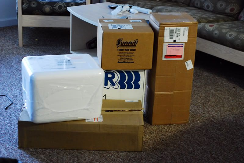
Then my roommate and I started getting serious. Here we have two sets of bilstein sport struts and shocks (BMW E30 and Audi 200 20v), eibach coil springs (200), H&R race springs (E30), A1 racing coilover parts, and Omaha steaks...
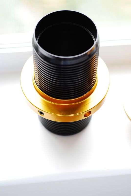
semi-finished product of the suspension setup
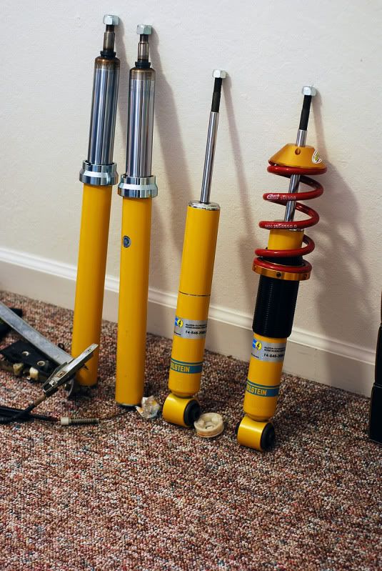
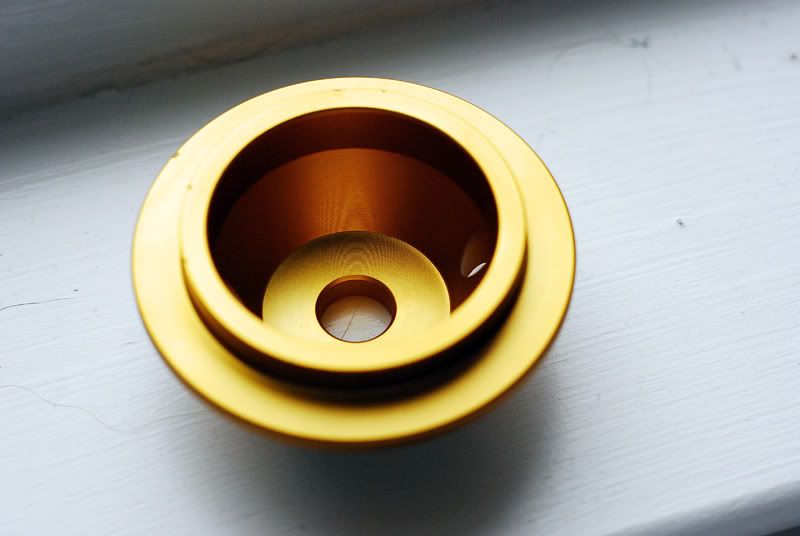
and for the fronts I had to make my own rings for the sleeves to sit on (strut housings)
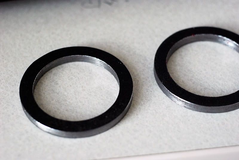
when all was said and done, we ended up with this

You can find more detail about coilovers ? There is a great desire to put himself .. The stiffness of the springs and the understatement of standard shock absorbers are not happy at all ....
Thanks
Re: Chris' 200 20v Revver Project
Posted: Wed Nov 19, 2014 8:28 am
by WOMBAT
AudiQuattros wrote:
You can find more detail about coilovers ? There is a great desire to put himself .. The stiffness of the springs and the understatement of standard shock absorbers are not happy at all ....
Thanks
Here you go!
http://www.theprojectpad.com/viewtopic.php?f=28&t=533
Re: Chris' 200 20v Revver Project
Posted: Wed Nov 19, 2014 8:42 am
by AudiQuattros
thank you very much!
Re: Chris' 200 20v Revver Project
Posted: Wed Nov 19, 2014 8:59 am
by loxxrider
Thanks Casey.
Jeff got in touch with me about head progress. We were waiting for some fancy, custom valve guides to be made. Now they're in and progress can be made again.
Re: Chris' 200 20v Revver Project
Posted: Sun Feb 01, 2015 1:14 am
by loxxrider
Update time! Finally!
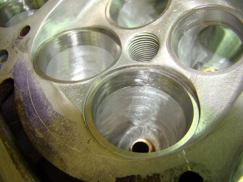
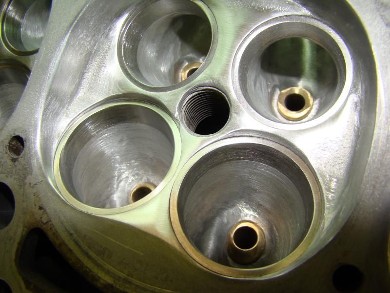
Jeff has been working on my head again. The work involves matching the valve seats to the ports and then blending the combustion chambers into the valve seat cutout. This is seriously impressive stuff and insane attention to detail. Jeff says this will absolutely be the best head he's ever done, and he won't do it (hand porting like this) ever again LOL! Too much damned work. I feel lucky to have the opportunity to have this on my engine. Not to worry though, I hear of some CNC rumblings going on here and there. Also, Jeff has some fancy new stuff up his sleeve that he wont tell me about, but I believe this engine will benefit from whatever it is
"Got my newly designed guides in and have them installed. Spent the day today installing the oversize seats and getting them ported into the head."
...
"Next step is bringing the chamber face down to the seat faces. We don't want anything impeding low lift flow and no sharp edges left from the seat pocket machining. You will see the height difference if you look closely at the pics." (this is shown in the second two pictures)
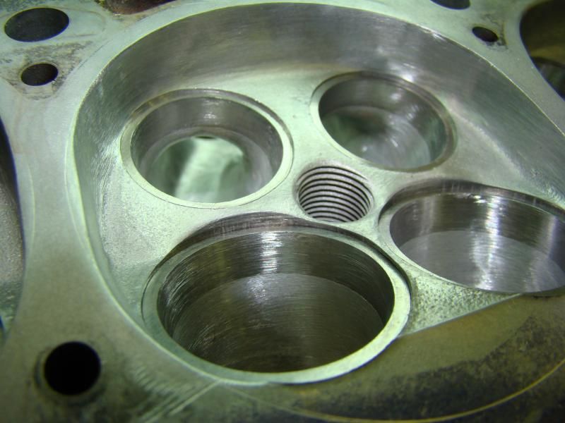
"Chamber massaging done ready to cut valve seats."

That's all for now. Hope this thing picks up after the head is finished!
Re: Chris' 200 20v Revver Project
Posted: Sun Feb 01, 2015 11:18 am
by AudiSport4000
Dang! That is sexy.
Id feel awful if anything ever happened to it.

Looking forward to more, kind sir.
Re: Chris' 200 20v Revver Project
Posted: Sun Feb 01, 2015 3:34 pm
by PRY4SNO
Well done!

